Resources to help protect your fisheries
Snail Barrier Installation

Overview
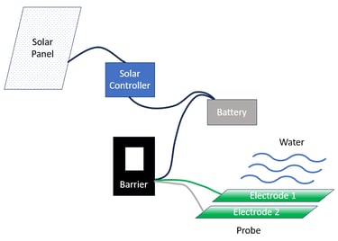
Here is a high level view of the Snail Barrier Installation...

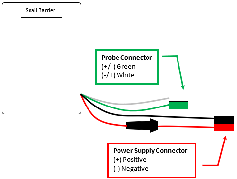
Controller
Connect the Probe (electrodes) to the Green / White connector and the Power Supply to the Red / Black connector. The Power supply should be between 7 and 30 Volts. The Snail Barrier will automatically power up and the display will show a title banner, start pulsing then display barrier measurements and status.

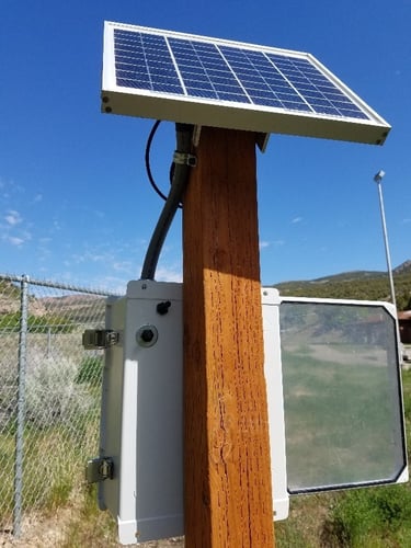
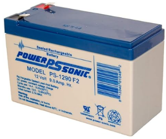
Power Source
The snail barrier is generally powered by a sealed lead acid battery, although any type of battery would work that provides sufficient voltage and current to handle the load resistances of the water. Typically, a 12 Volt sealed lead acid battery is used. See the appendix for proper battery amp-hour sizing.

Probe Overview and Installation
The probe generally consists of two stainless steel strapping bands, called electrodes, secured to an insulated, immovable substrate separated with a rubber cushion in-between. The rubber cushion is used to eliminate any small gaps between the electrodes and the mounting substrate so the NZMS do not crawl under the electrodes. The two electrodes are separated horizontally by 1/8 inch. Gaps wider that 1/8 inch have not been examined extensively to determine their effectiveness. However, if these electrodes are spaced further apart the current density will decrease reducing the barrier strength. This probe assembly must be located underwater to be effective at blocking the NZMS from traveling upstream crawling along channel surfaces.
The probe substrate must be secured to the water channel in such a way to prevent these tiny snails from traveling underneath the probe and mounting surface. This is why a rubber cushion is also used underneath the mounting substrate. Mounting holes are drilled in the substrate to secure the probe assembly to the bottom and sides of the water channel. If possible, the connection point of the wires coming from the controller to the probe should be located outside of the water. This connection point can corrode very easily thereby making the snail barrier ineffective.
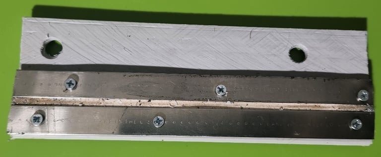
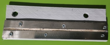
Fig 1 Top View of Probe
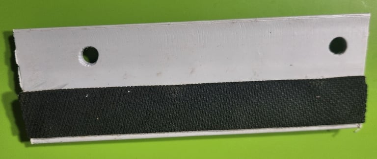
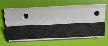
Fig 2 Bottom view of probe mounting substrate
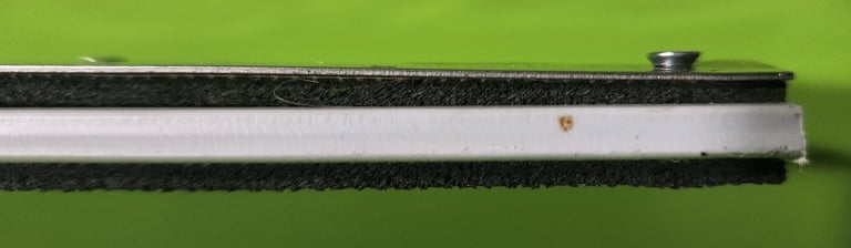
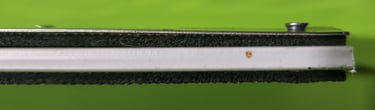
The probe front view as shown in Fig 3 is what the NZMS sees and they only have one option which is to crawl over the top of the electrodes.
One stainless steel strap will serve as the positive electrode and the other the negative. Once the electrodes are placed under water the circuit is completed and snails will be shocked as they physically move between the two electrodes. This causes them to release their grip on the channel surface and will be washed downstream. Contacting a single electrode will not cause the snails to be shocked. The snail barrier will change is polarity about every 24 hours to minimize corrosive buildup.
Royal Building Products 1-1/2-in x 8-ft PVC Lattice Moulding (Lowes)
Foam Tape: Continuous Roll, Black, 1 in x 16 8/8 yd, 1/8 in Tape Thick, Rubber Foam
Stainless Steel Band: 0.03 in Strapping Thick, 1,500 lb Break Strength, 50 ft Strapping Lg
Tapping Sheet Metal Screw: #6 Size, 3/8 in Lg, 18-8 Stainless Steel, Plain, Flat, Phillips
CAROL Hookup Wire: 18 AWG Wire Size, Red, 100 ft Lg, 300 V Volt
CAROL Hookup Wire: 18 AWG Wire Size, Black, 100 ft Lg, 300 V Volt
Fig 3 front view of probe
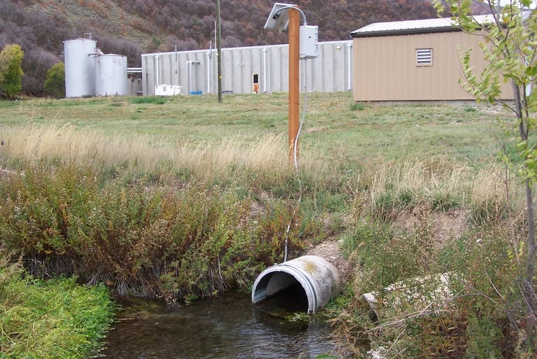
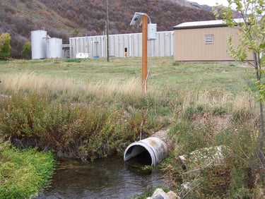
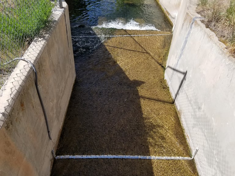
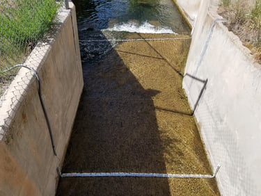
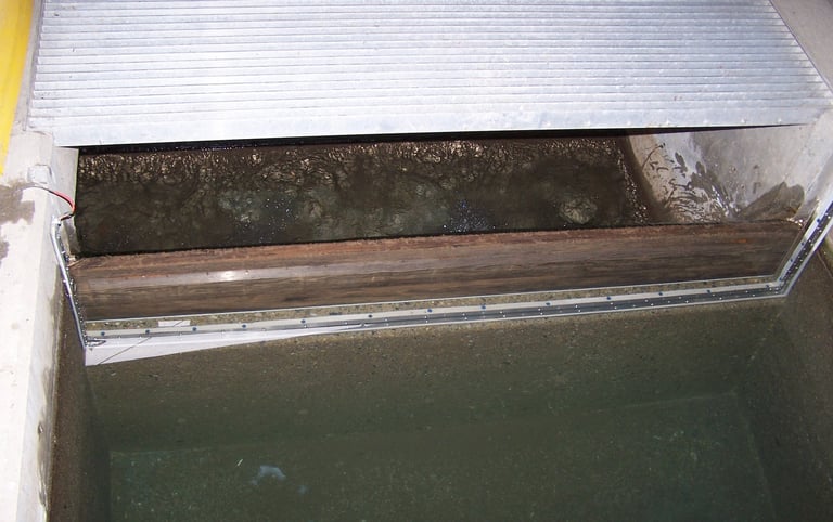
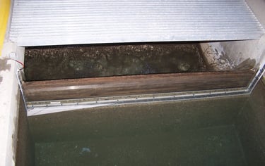
Probe Installation in a Channel
Here are a few examples of a probe installed install in a channel.
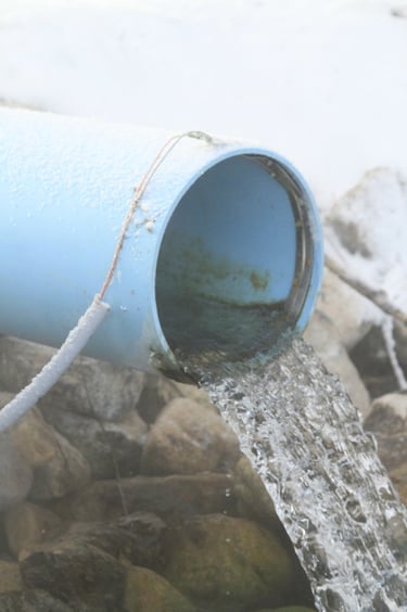
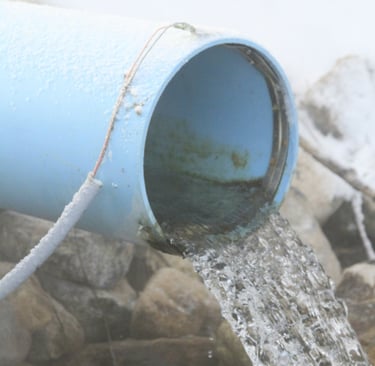
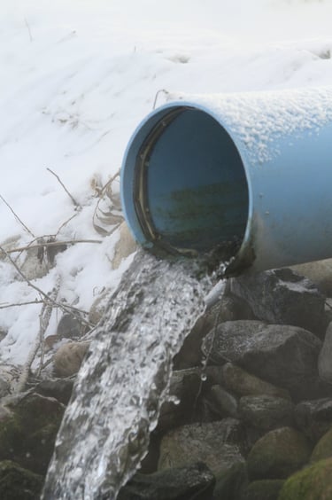
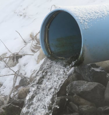
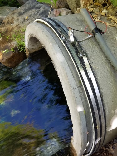
Probe Installation On Pipe
Probes can either be installed on the inside or the outside of a pipe. On the outside of the pipe, you can use the Band-IT clamp tool. You can follow instructions that come with Band-IT tool on how to operate tool. To install the probe on the outside of the pipe no part of the pipe can be buried in sediment or vegetation. The pipe needs to be partially covered in water. In no water is in contact with the outside of the pipe then the probe should be installed on the inside of the pipe. When installing the probe on the inside of the pipe only the stainless-steel bands, the rubber cushion and stainless-steel screws are needed. An important thing to note is that it is imperative that there are no air gaps between the rubber cushion and the pipe. It is also very important to maintain the 1/8” gap between the stainless-steel bands anywhere the probe will come in contact with the water.
BAND-IT Band Clamp Tool: 0.1875 in Min. Strapping Wd, 0.75 in Max. Strapping Wd, 8 in Tool Wd
Strapping Buckle: Fits 1/2 in Strap Wd, 201 Stainless Steel, Flat, 50 Qty, 50 PK
Here are some examples of a probe installation on a pipe.

Creative solutions for aquatic ecosystem preservation.
© 2025. All rights reserved.