Resources to help protect your fisheries
Controller Operation
Operation of the snail barrier is very simple. It is plug and play operation. There is no on / off switch or user settable options. Once power is applied the controller will begin to pulse at the designated rate which is a 25 millisecond on time and a 3 second off time.
Boot Sequence
When the controller is first powered up it follows the sequence:
1. Pulse positive polarity (Blue Dot)
2. 3 Second delay
3. Pulse negative polarity (White Dot)
4. 3 Second delay
5. Pulse positive polarity (Blue Dot)
6. 3 Second delay
7. Pulse negative polarity (White Dot)
8. 3 Second delay
9. Pulse positive polarity (Blue Dot)
10. 3 Second delay
11. Pulse negative polarity (White Dot)
12. 3 Second delays
13. Pulse positive polarity (Blue Dot)
14. Normal pulse operation begins
The pulse count and the number of pulses before polarity toggle is shown on the bottom line of the display if there are no errors or warnings.
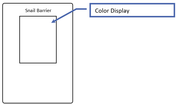
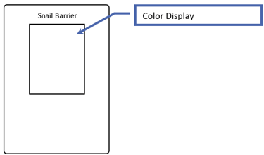
Color Display
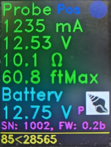
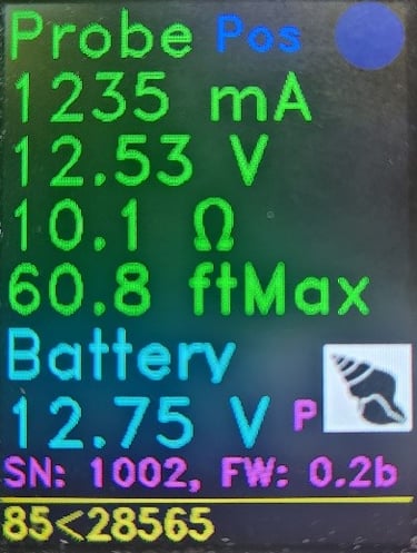
The color display shows all probe measurements, pulse status, pulse polarity, serial number, firmware version and messages on a single screen.
Probe Measurements
Three measurements and one quality factor are displayed for the probe.
Probe Current
The probe current is measured 10 times and averaged during the pulse on time. The current is displayed in milliamps (mA). The higher the current the stronger the electric field is between the two probe electrodes and the longer the probe length that can be supported.
Probe Voltage
The probe voltage is measured 10 times and averaged during the pulse on time. Typically, the probe voltage is a little less than the battery voltage. However, this voltage drop can become larger as the probe current increases.
Probe Resistance
The probe resistance is calculated as the probe voltage divided by the probe current. The measurements unit for resistance is ohms (Ω).
Probe Effectiveness Quality Factor
This quality factor is based on the current density for a probe electrode spacing of 1/8 inch. This quality factor is given as a length of probe that can be effective given proper probe installation. If the probe length being used is less than this quality factor length the barrier will be effective in preventing snails from crossing. If the barrier length is longer than the quality factor length that does not mean that the barrier is not effective rather it means that testing has not been done at that current density so the barrier effectiveness cannot be guaranteed. For example, the display picture in this document shows a probe quality factor of 60.8 ftMax. This means that any length of probe less than 60.8 ft will be effective as preventing snail crossing assuming proper probe installation.
Battery Measurements
Battery Voltage
This is the measured battery voltage. If the battery voltage is less than 10.8 volts a low voltage warning will be display. Sealed lead acid batteries do not like to be over discharged.
Device Information
The serial number and firmware version of the barrier are displayed. There is also a letter designating the type of device (B – Snail Barrier). The adjacent icon displays the current operating mode of this device. A picture of a snail indicates the device is operating in Snail Barrier.
Pulse Status
The status of the pulse is displayed in as a pulsing dot in the upper right corner of the display. The dot appears during the probe on time, when power is applied to the probe load.
The color of the dot indicator has different meanings.
· BLUE – Normal pulse operation. Polarity (green terminal) is positive.
· WHITE – Normal pulse operation. Polarity (green terminal) is negative.
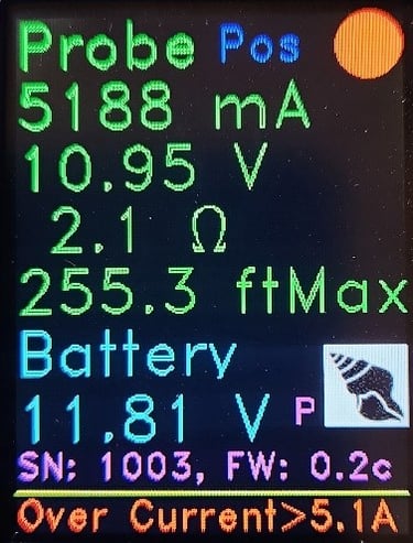
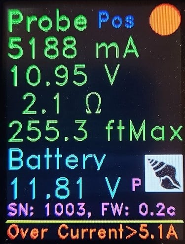
· RED – No pulsing. Shorted probe detected.
Indicates an over current state has been reached. The probe pulsing is stopped for 1 minute and the device will reset and begin is pulsing again. If the reason for the over current condition has not been resolved the process will be repeated.
The words Pos or Neg are displayed next to the pulse indicator dot to show probe polarity also.
Warnings and Errors
Warnings and errors are displayed on the bottom line of the display in red. The messages are:
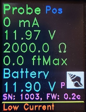
· Low Current (Probe Current < 18 mA)
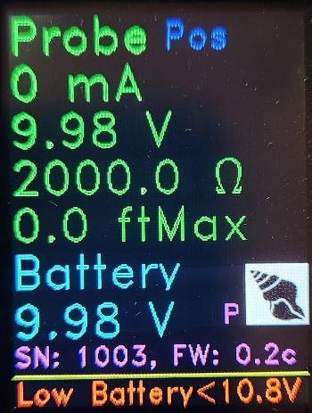
· Low Battery Voltage (Battery Voltage < 10.8V)
· Over Current (Probe Current > 5100 mA)
Low Current
This error message generally indicates that the probe is not connected to the controller.

Low Battery Voltage
Generally, indicates that the battery is not being charged or that the solar panel is undersized and cannot keep up with the current required by the barrier.

Over Current
This typically means that the probe electrodes have been shorted. When this happens this error message is displayed, the probe status dot will be changed to red and the controller will stop pulsing to protect the controller from destroying itself. After 1 minute the controller will restart and an attempt will be made to start the pulsing again. If the short still exists the process will repeat.
Pulse / Toggle Count
The pulse count and the number of pulses before polarity toggle is shown on the bottom line of the display if there are no errors or warnings. For example, the display at the beginning of this section shows 85 pulses have occurred either since power up or the last polarity toggle. When the pulse count gets to 28565 the probe polarity will toggle and the pulse count will begin again.
Operation Summary
There are two primary indicators that show barrier effectiveness.
1. No red error or warning messages
2. The Barrier Effectiveness Quality Factor (BEQF) has a longer length than the underwater probe length.
3. The Battery Voltage for a sealed lead acid battery is typically between 11.0 and 13.0 Volts.
4. The Probe Voltage is typically equal to or a few tenths of a volt below the Battery Voltage.
5. The Probe Current can vary from installation to installation. If the BEQF is longer than your underwater probe length you do not need to worry about this measurement. However, it should remain fairly constant over time. If this decreases substantially over time it typically indicates the probe is dirty and needs to be cleaned.
Creative solutions for aquatic ecosystem preservation.
© 2025. All rights reserved.